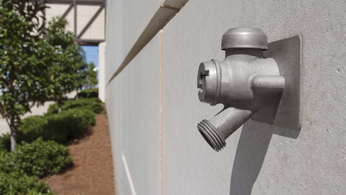
A request was made to explain the differences between the ASSE Standards 1011, 1019, 1052, and 1053.
- ASSE 1011: Hose Connection Vacuum Breakers
- ASSE 1019: Vacuum Breaker Wall Hydrants, Freeze Resistant (Type A, B, C Automatic Draining Type)
- ASSE 1052: Hose Connection Backflow Preventers
- ASSE 1053: Dual Check Backflow Preventer Wall Hydrants, Freeze Resistant
A hydrant bearing any of these designations has been tested at a recognized and listed third-party testing laboratory who certifies the product conforms to the requirements of the referenced standard. Some products may not meet certain parts of the standard or have not been tested by a third-party laboratory, and therefore cannot display the standard designation on the face of the product.
ASSE 1011: This strictly refers to the vacuum breaker you will see on many hydrants and hose bibs. It does not matter whether it is integral or an add-on, as long as it contains the 1011 designation. Again, the 1011 is in reference to the vacuum breaker—not the hydrant. Many codes require hose bibs to have vacuum breakers even after installation. Most vacuum breakers will prevent the hydrant from self-draining so the disc and/or diaphragm may need manipulating to drain any water captured in the hydrant after shutting it off to avoid the hydrant from freezing. There are types available with automatic drainage features. Some vacuum breakers are removable while some are permanently attached.
ASSE 1019: This standard establishes design and performance requirements for wall hydrants, requiring that they be freeze resistant, automatic draining, and contain an integral and permanent device to prevent backflow due to back siphonage, back pressure or both.
There are three hydrant classifications under this standard:
- Type A devices protect against back siphonage and back pressure and contain not less than two mechanisms (at least one mechanism shall be a check) to protect and relieve back pressure. The hose shall be removed to prevent damage from freezing.
- Type B devices protect against back siphonage and back pressure and contain not less than two mechanisms (at least one mechanism shall be a check) to protect and relieve back pressure. The hose need not be removed to prevent damage from freezing.
- Type C devices protect against back siphonage and back pressure and contain not less than one mechanism to protect against back pressure. The hose shall be removed to prevent damage from freezing.
ASSE 1052: This standard establishes design requirements, basic performance requirements, and test procedures for hose connection backflow preventers. This device is designed to be installed on the discharge side of a hose threaded outlet on a potable water system. This two-check device protects against backflow, due to back siphonage or low-head back pressure and is field testable to certify protection under the high hazard conditions present at a hose threaded outlet. These devices shall not be subjected to continuous water pressure.
ASSE 1053: This standard establishes design and performance requirements and test procedures for Dual Check Backflow Preventer Wall Hydrants, Freeze Resistant. The purpose of these devices is to provide protection of the potable water supply from contamination due to back siphonage or back pressure without damage to the device due to freezing and is field-testable to verify protection under the high hazard conditions present at a hose threaded outlet. These devices shall not be subjected to continuous water pressure. Basically, the 1053 is a combination of both the 1019 and 1052 standards.
ASSE reviews each standard every five years. At this time they are re-affirmed with no changes or a committee is formed to appraise suggested changes and revisions. Presently, committees have been formed to start this process for three standards: 1010 Water Hammer Arresters, 1011 Hose Connection Vacuum Breakers, and 1057 Sanitary Yard Hydrants. Smith will be represented on each committee.
Grease Interceptor Flow Control Fitting
The flow control does more its name implies; it also enhances the separation process and overall efficiency of the grease interceptor.
Operating as a kind of safety valve, the flow control device regulates the velocity of water as it drains. Controlled flow rate protects against overloading the unit and ensures maximum performance. It is essential in order to obtain the 90% or better efficiency rating required to pass the PDI-G101 Standard testing criteria.
The fitting is constructed with an air intake, drawing in air as the grease-laden wastewater passes through. Once it reaches the interceptor, the wastewater passes over a series of separator baffles, and the entrained air rises rapidly to the surface. The released air provides a small amount of positive pressure above the contents of the separation chamber, regulating the internal running water level of the grease interceptor. In addition, the escaping air pulls grease globules with it to the top.
Download the original newsletter here: Vol. 1, Issue 8: ASSE Standards 1011, 1019, 1052 & 1053 for Hydrants
